I poked around on the Internet looking for a schematic for the HM-219 hand mic. Believe me, Icom didn't make it easy to find, but eventually I came up with a few helpful results I was able to piece together.
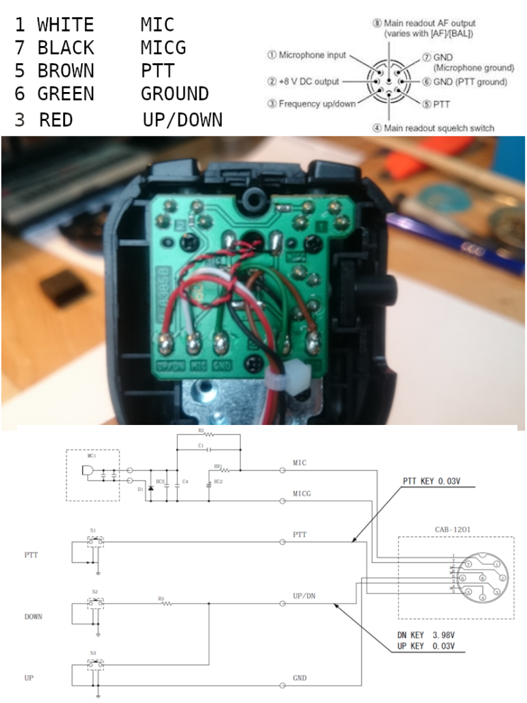
Now, I know that if I'm going to build my own headset, I will need to come up with an acceptable microphone. Since I liked how the mic in the HM-219 sounds, I decided I will take that and figure out how to get it mounted on a boom. There is also the small matter of a diode, a resistor, and a couple capacitors that must be placed between the mic element and pins 1 & 7 on the mic jack. In order to make this microphone perform as similarly as possible to the HM-219 I will need to locate this bit of circuit near the mic element - a problem for later. For now, I just want to verify that what I've found on the Internet is correct.
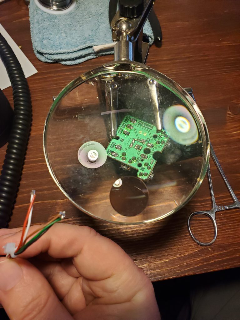
I started taking apart the HM-219. A small phillips head screw driver got things started.
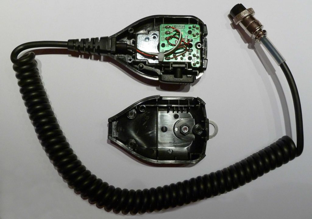
I compared the color codes and labels on the PCB. Everything matched up. So far. so good.
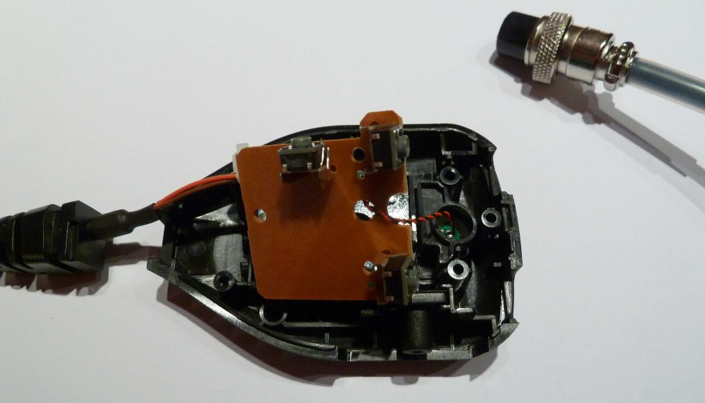
The PCB from the mic body is too big to tuck into the new headset, and I wouldn't want the PTT and Up/Down switches anywhere up there, so I decided I wouldn't be reusing that for this project. However, I could certainly use the mic cable and element, so I broke out some more tools.
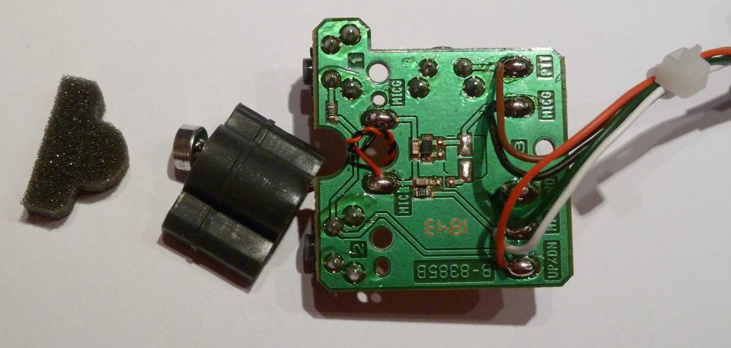
Here the silver mic element is seen to the left between the foam and the plastic housing which holds it in position inside the body of the hand mic.
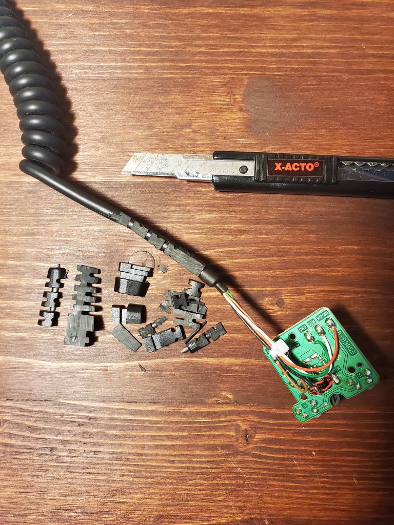
The mic cable included a fat section of strain relief molded around the outside where it seats inside the hand mic body. I won't be able to use that oddly shaped custom fit for my project, so I used an exacto knife and carefully trimmed away the strain relief. I will have to come up with my own solution for this later.
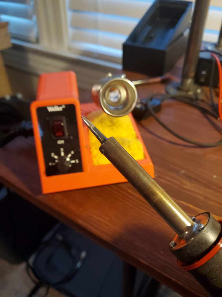
It only took a few seconds for my trusty iron to free the mic element and cable from the PCB. These are the only two parts I will be salvaging. The rest will go into the scrap parts bin if I am happy with how the headset turns out. Otherwise, I will just put the HM-219 back together (with alternate strain relief).
In Part 3 I will salvage the rest of the parts I'll need and begin some rough proof of concept testing. Stay tuned!

This amateur radio hobby can be quite expensive. I've tried to be patient and frugal, and it has paid off. I'm fortunate to have acquired some quality used gear at affordable prices. Two of the transceivers on my desk currently are the Icom IC-7300 and IC-9700. These radios look and behave very similarly, and together they cover nearly every band and mode a US operator is likely to care about.
Each transceiver comes with a hand mic, the HM-219.
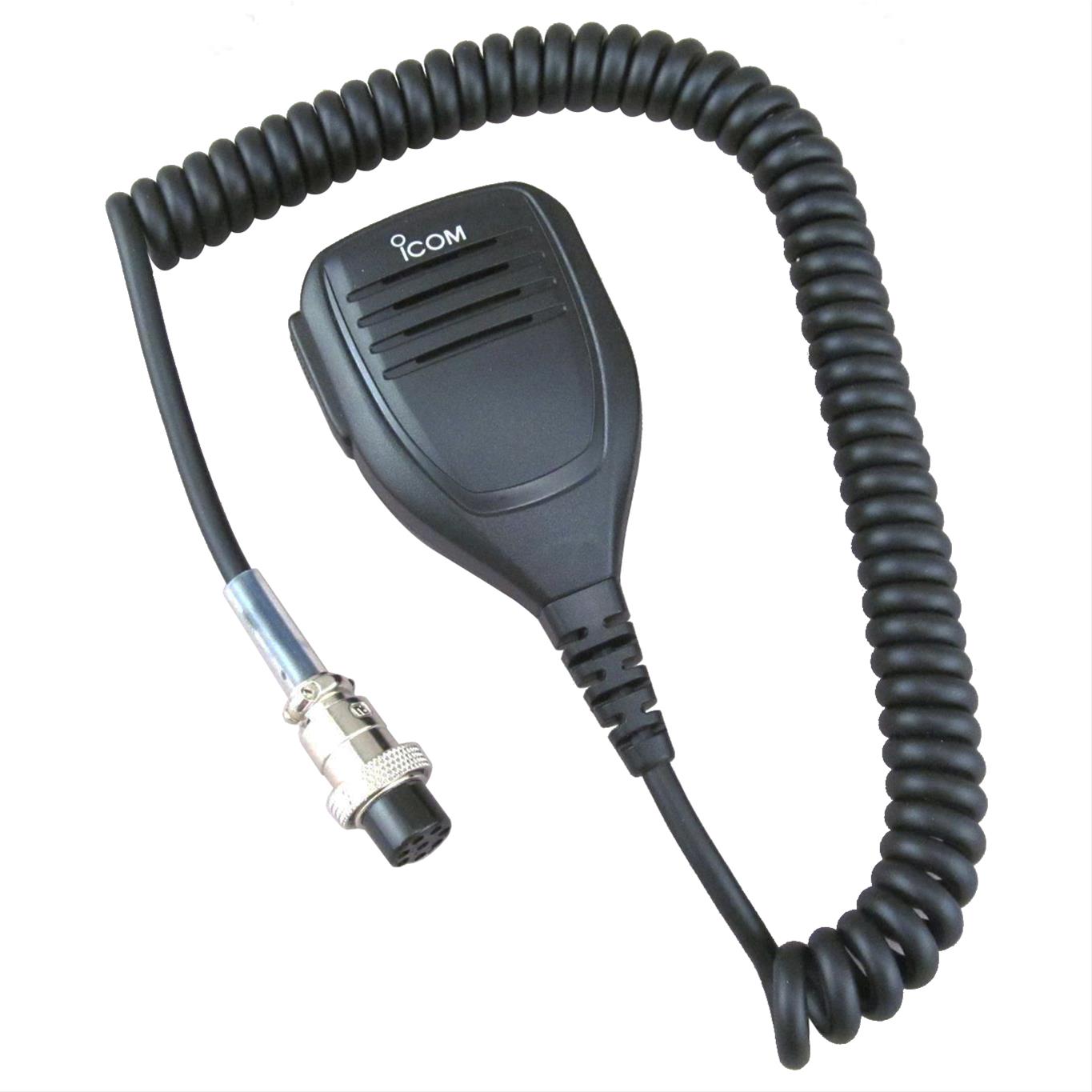
I'm very pleased with how well this mic works. To my ear, it sounds quite good compared to a half dozen much more expensive vocal mics I've tried with these radios. The interesting thing about microphones in the amateur radio hobby is that an expensive mic designed for vocal performance is not necessarily going to be a superior performer in the squashed limited bandwidth of amateur radio.
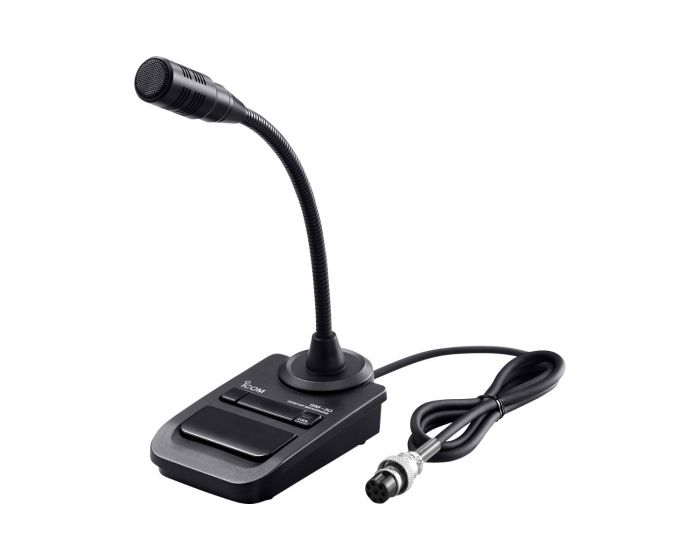
The thing is, I don't really like to use the hand mic, no matter how good it sounds. I prefer to have my hands free. So, I purchased the SM-30 desktop microphone. This has been a useful addition to my Icom radios. It uses an electret element just like the hand mic, sounds just as good, and once I set the gain and compression and EQ for one mic it works for both. It also has a PTT lock, so if I'm giving an extended rag chew I can be hands free.
Now, here is the problem. Neither of these mic solutions is ideal. The desk mic's hands free capability is beneficial in certain situations, but I have to sacrifice the Up/Down switches found on the hand mic. I miss these when I'm working from saved memories on the IC-9700. And neither of these mics makes it easy to keep the element positioned at a consistent orientation and distance from my mouth. For best results, I want placement consistency.
What I need is a headset. But it has to tick the following boxes:
- The mic element performs at least as good as the HM-219
- The boom reliably positions the mic where I need it
- The headset is comfortable enough that I could leave it on for hours
- The speakers sound at least as good as the radio's and are loud enough
- There is a convenient way to use PTT and lock it.
- There is a convenient way to select Up/Down
- I can switch to one of my other mics without having to go menu diving
That last bullet point is the one I've been stuck on. I know there are some nice commercial headset options out there, but none that I'm aware of will be easy to swap out in a pinch. Suppose I'm using a headset and someone drops by my shack. Being a polite person, and never wanting to miss an opportunity to expose someone to this great hobby, I instantly switch from my headset to SM-30 desk mic and speaker, including my guest in the fun. That is not the moment I want to start receiving poor audio reports, and I don't want to get lost in a menu tree. If I have to mess with a bunch of settings to make the mic swap work out, it just won't be worth it.
I have not given up. In fact, I have a plan. I've decided to build my own solution salvaging parts from one of my HM-219's, an old David Clark aviation headset I picked up at a garage sale, a well used PC headset now sitting in my junk parts bin, and a little ingenuity.
Stay tuned.
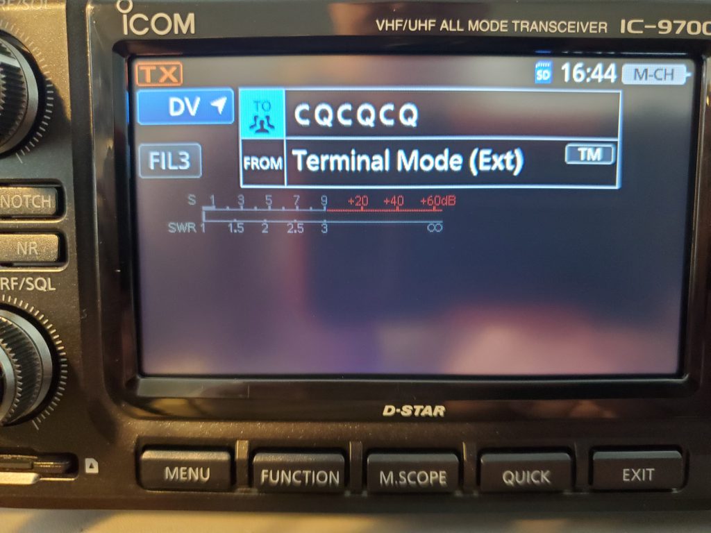
There are multiple ways to set up and use DSTAR on the IC-9700, each with pros and cons. The Terminal Mode using the External Gateway function is great for two reasons:
- It is easy to configure. There are only a few things to configure on the IC-9700, and a few settings on the hotspot. I'm using a Raspberry Pi running Pi-Star.
2. It eliminates RF (even WiFi if you like), instead using cabled connections from the radio to the gateway and beyond. Minimize possible problems!
I set this up in my shack using the OPC-2350LU cable that had long been tucked away deep in my ID-51 accessories bag.
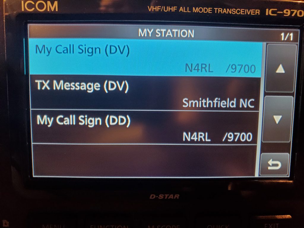
First, just as you would with any method of using DSTAR, register your callsign with a gateway server local to you. I also went to MENU > SET > My Station > and set My Call Sign (DV), as well as My Call Sign (DD), using my call sign and a suffix to represent my radio, like so "N4RL /9700". I also decided to put my City and State in the optional TX Message (DV) field.
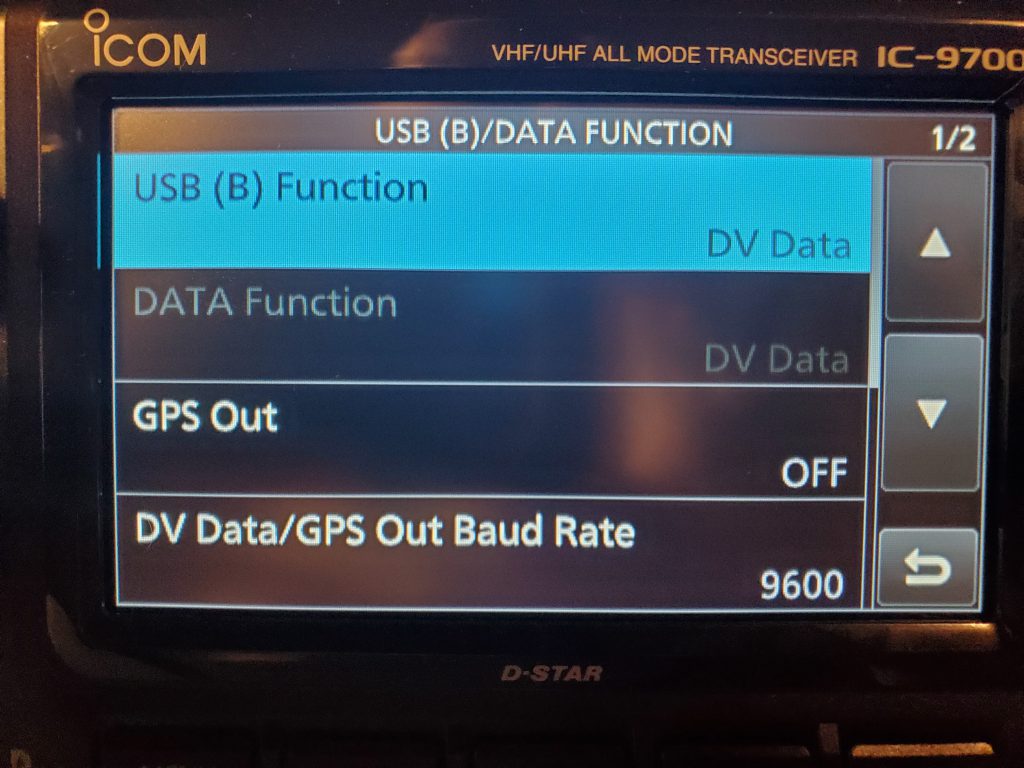
Next, go to MENU > SET > Connectors > USB (B)/DATA Function > and set it to DV Data.
And last of all, go to MENU > 2 > DV GW > and set Gateway Select to External Gateway (DATA). This is also where you will select <<Terminal Mode>> to connect to your gateway. Once, again, I'm using a Raspberry Pi running Pi-Star.
I'm finding it handy to just go into the Pi-Star console to see the action and manage reflector linking from there. I will do a separate post on how I have the Pi-Star set up.

If you find yourself in the market for a new pickup truck, and you have more than a passing interest in off-grid power, then you HAVE TO check out what the wizards over at Ford Motor company have been cooking up in the 2021 F-150.
Like many other auto makers, the gasoline powered models have optional built-in AC inverters, but these are notoriously underwhelming, typically topping out at a few hundred watts or so.
Ford put the competition on notice and grabbed my attention with the introduction of their 7.2kW system available on the F-150 hybrid. This is a big step up from the rest.
It draws first from the battery before firing up the engine. But unlike the lesser versions, it offers four 120-volt, 20-amp outlets and one twist-lock NEMA L6-20 240-volt, 30-amp outlet and can provide up to 7,200 watts of electricity. For reference, that about double the power available on typical RVs.
I can think of all kinds of off grid uses for that power plant, starting with running amateur radios on field day, and powering my house when grid power is out. The fact that its unparalleled in its mobility and ability to carry the stuff I want to power makes the new F-150 a dream truck.
I'll need to start saving my pennies.

In a survival situation, you have to prioritize your effort and get the most urgent and important things going. At the top of the list is first aid. We aren't talking about minor quality of life treatments here. This is basic life support kinds of first aid - breathing and bleeding - the things that are time sensitive within minutes as opposed to hours or days.
When critical first aid is stable, then you move on to the next category which is fire and shelter. In winter you focus on fire and then on shelter that will capture and hold heat. In summer you focus on shade and airflow, then on fire. You need to have a basic shelter and fire going within a few hours.
In some cases, it may be a challenge to get this work done quickly. You may be in a resource poor environment. You may get a late start with little or no daylight. You name it. So, having a few science-based principles and a few memorized tricks up your sleeve can make a big difference. Imagine how helpful it would be if you could get your fire going right away, so you could move on to shelter tasks.
I thought I would share some of the emergency tips and tricks up my sleeve for getting a fire going fast, using less common items as tinder or accelerants.
First Aid Kit
You probably have things that burn really well right in your kit. Cotton balls, alcohol wipes, gauze bandages and dressings, and Vaseline, are potent fire starters. So remember to go to your First Aid Kit and use your available resources.
In case you weren't aware, home made fire starters constructed from Vaseline and cotton balls have been a well known backpacker trick for many years.

Hygiene Products
Feminine products, tampons, pads, tend to be slow but reliable tinder. Kotex pads are a good choice. Also in this category you'll have good success raiding the medicine cabinet for rubbing alcohol, nail polish remover, and hand sanitizer. Actually hand sanitizer deserves a special shout out. Depending on the brand, its a miraculous napalm-like substance.

One more noteworthy mention in this category is lip balm. A tube of Chapstick, an improvised wick, and some muscle can quickly result in a long burning DIY candle.

Aerosols
Best known in this category is the aerosol spray can flame thrower. The propellant is the flammable point of greatest interest here, rather than the substance the propellant is delivering. However, generally you can avoid aerosol food products, as they tend to use non-flammable propellants. You want hydrocarbon propellants. Things like paints and cosmetics are almost always excellent choices. Bug spray, sun screen, WD-40, and all sorts of chemical sprays are great choices too.

Foods / Snacks / Condiments
Powdered nondairy coffee creamer is like magic fire dust. Sprinkle it where you need an accelerant and stand back. I'm not a coffee drinker, but when I was in the ARMY, I used to squirrel away coffee creamer packets from field rations. Opportunities for building a fire were rare, but when permitted, I used that creamer to get my fire going quick.
Fritos, Doritos, Cheese Puffs, and lots of other high fat chips make great fire starters. No one wants to sacrifice nacho cheese goodness, but when you don't have normal tinder resources, use what you've got!
Bacon is a fantastic magical food, high in fat content. This one is a bit of a chicken and egg problem, as you need a fire to separate the fat and liquify it, but if you can manage that, you'll have both a delicious treat and a collection of grease for future fires. Use this tip when the power is out, you're getting low on combustibles, and you need to make your own light / heat until power is restored.
Garlic is a full of natural oil. Its a good burner. If you are desperate for kindling toss your garlic in the fire.
Orange peels are nice burners when they are dry. Even fresh orange peels will burn a bit due to the natural oil they contain - a fact that bartenders use to make certain fancy cocktails, or so I am told. When the peel is dried out, it burns much better, as you probably guessed.
In a pinch, if you cut an orange in half, eat the meat, save the peel, you could then use that bacon grease we talked about, or some used cooking oil, etc, and pour it into the orange peel half. If you were careful when digging out the orange, you kept a natural orange wick, but if needed you can improvise a wick from some other material. Viola - you have yourself a nice little orange candle. Rest an inverted clay pot over the top and you have a small heater.
Do you have any favorite tips and tricks, or less common combustibles you would recommend in an emergency?
I needed a new battery charger for my deep cycle AGM battery pack I showed in a previous post. I thought about building one out of parts from some old computer power supplies, but I ran into a good deal on this smart charger from Schumacher. The model number is SC1358. It's designed for all kinds of Sealed Led Acid batteries, regular and AGM, both starter batteries and deep cycle, both 12v and 6v.
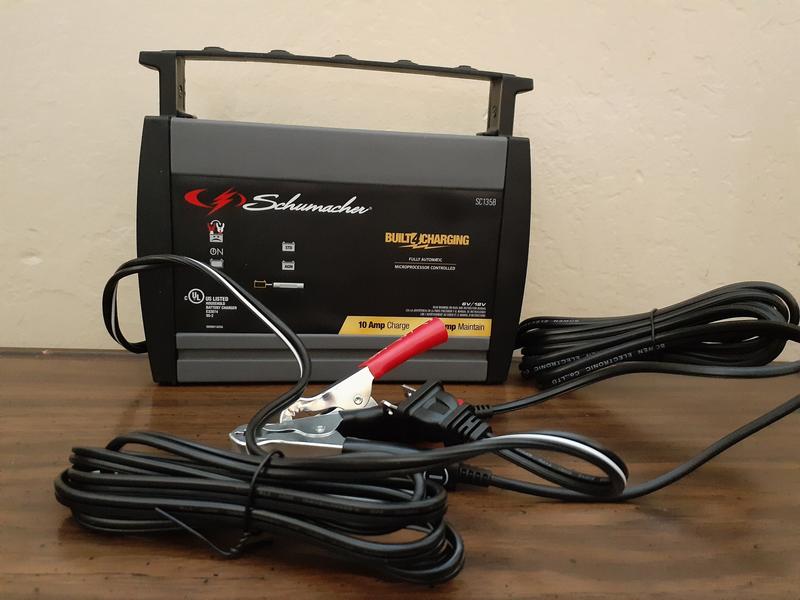
This charger has a built-in microcontroller which allows it to do some helpful things. It detects the battery type when you connect it. If you mixed up the cables, it will go into protection mode and light up an error indicator. It also determines the ideal voltage and rate of charge for the battery. It has a maximum 10a charge rate and 3a maintenance rate.
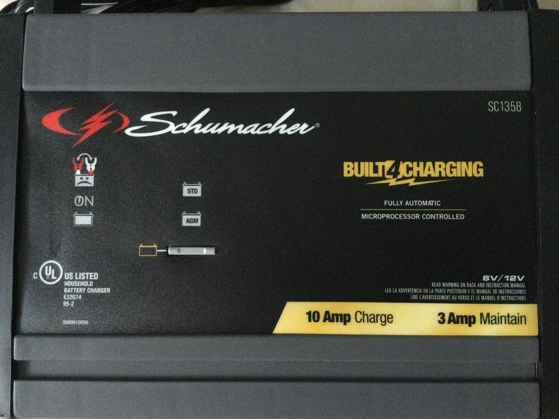
I've been using this charger for a full year now and it continues to impress me every time I use it. Its super convenient, reliable, idiot-proof, and seems to be durable.
At some point in the future I will probably replace all of my lead acid batteries for modern chemistry alternatives, but as long as I still have any SLA's I will be holding on to this charger. Its a keeper.
Remember when you were a kid and every map you saw showed that Greenland and Antarctica were massive bodies of land? Then you grew up and at some point you realized that the world is a little different than you thought. That is, of course, because we mainly use Mercator maps. These maps represent the globe as a cylinder, which we then press out flat, because flat maps are easy to use, but our world isn't flat, and its not a cylinder. Its a sphere. Because of this, things represented on a Mercator map appear skewed in size, distance, and in shortest path direction.
Less common, but extremely helpful, is the Azimuthal map. This kind of map is also flat, but it is constructed so that everything on the map is equidistantly projected from the center. If you make the center of the map your current position, then you will have a very easy time of finding an accurate azimuth and distance to any other point on the map. This doesn't mean everything will be represented in its actual relative size. We still have the problems inherent in converting a sphere to a plane, but at least you will have correct directions and distances to points of interest.

In the example above, we are centered on Antarctica. Notice that it is no longer a massive continent dominating the map.
COMMERCIAL AZIMUTHAL MAPS
You can get professionally printed full size color maps from Mike Whitehead, callsign GM0PHW. I bought a map from him a little over a year ago from his website http://www.dxmaps.co.uk There was some sort of hang-up in customs, or mail, or something. I contacted Mike and he was A+ in customer service. He printed and sent me another map at no cost. I received it and a day later the original map finally arrived - go figure. He makes a great product and will take care of you. Here is an example of his work

FREE AZIMUTHAL MAPS
Tom Epperly, callsign NS6T, provides a free online tool to generate your own azimuthal maps. You can input a position of your choosing, select a radius distance, and turn on/off city, state and country labels.
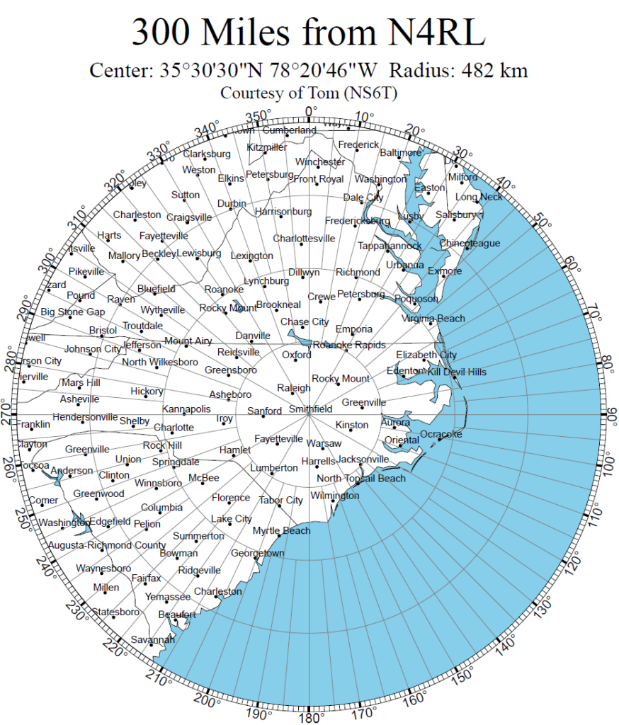
I used this to create a few custom maps for use in my shack: 2m VHF with a 80 mile radius, HF NVIS for EMCOMM use with a 300 mile radius, and a US DX map. Check it out for yourself at https://ns6t.net/azimuth/
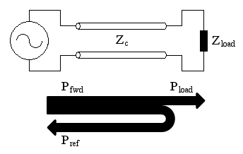
Recently, I have posted back to back about maximizing power at the antenna, and about characteristic impedance. These conversations have touched on reflected waves and associated loss. I thought it might be good to drill down on this just a bit more, as these have been topics on my mind as I have been making changes to my humble ham shack.
I like a good analogy. When imagining and describing RF radiating from an antenna, or traveling along a coax, we often describe it as waves. These waves can't be seen, but we can imagine some of their properties by substituting the behavior of visible, tangible waves we are familiar with - sea waves.

A big beach with a slow, gradual rise in elevation will allow waves to come in from the sea and slowly dissipate, using the majority of their energy to dampen the farthest inland reaches of the beach.
By contrast, an abrupt sea wall creates a violent place where an incoming wave crashes into the wall, sending spray into the air, and causing a new wave to instantly form and bounce back in the opposite direction. The new wave collides with the next incoming wave where their opposing forces interact. In the subsequent interactions, much energy which could have been used to dampen the beach beyond the sea wall, gets wasted.
We might say that our gradual beach example has a desirable characteristic impedance - well suited for the arriving sea waves to reach as much sand as possible. We could also say that the beach with the sea wall is poorly matched, and because of this the energy in the waves is reflected back out to sea where it interacts in ways that dissipate wave energy before the waves can reach the sandy beach.
Using a VSWR meter we can measure the magnitude of wave reflections happening in our system.
RETURN LOSS
Return Loss is the measure of how much power is being reflected from our load, which in our case is our antenna system. The better we do at matching the load to its “ideal” characteristic impedance, the lower the reflected power will be. We will always have some amount of reflected power. (Even in our gradual beach analogy, after each way reached its apex, there was going to be some water changing direction and making its way back toward the sea.)
This kind of loss is expressed in dB relative to the power we used to transmit. Since the value of the reflected power will always be less than the transmitted power, we express this value as a negative number. It is correct to think of RETURN LOSS as the amount of power reflected that didn't get absorbed by our load.
MISMATCH LOSS
There is another sort of loss that often gets lost in the return loss discussion, but it should be understood as something separate. This is mismatch loss. We introduce mismatch loss by including imperfect components into our antenna system. At every connector, coupler, adapter, and so forth we add an opportunity for a distinct change in characteristic impedance. These kinds of changes are hardly noticeable compared to typical return loss problems, yet they do contribute to overall loss. For this reason, we can try to minimize the possibilities for mismatch by using the fewest possible components in the design.
There are many different types of 50 ohm coax. Some thick, some thin, some rigid, some flexible. They also vary in factors of attenuation and RF leakiness, yet they are all said to be 50 ohm coax.
But what does it mean when we say a coax cable is 50 ohms? If I pull out a multimeter and test the center conductor of a coax jumper from end to end I won’t see 50 ohms of resistance. I will see it as a perfect conductor, with no resistance. Similarly, I could measure the shield end to end and get the same thing. If I touch one lead to the center conductor and the other to the shield, my multimeter reads infinite impedance. Finally, when I short the far end and measure again it now reads zero ohms. I can't find 50 ohms anywhere!
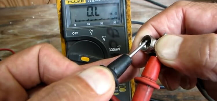
With a handful of exceptions, which I won’t cover here, we use 50 ohm coax in amateur radio. Our feedline, jumpers, connectors and all of our equipment is designed for a 50 ohm input impedance. Let's take a deeper dive.
RESISTIVITY
Resistivity is the term used to describe how resistive a given material is. Just as DENSITY describes the mass of a cubic meter of material, RESISTIVITY describes resistance across two opposite faces of a cubic meter of material.
Different materials have different amounts of resistivity. The resistivity of copper is 1.7 × 10⁻⁸
Other factors necessary to calculate the resistance of a given wire are its length and its cross sectional area. In other words, yes copper has some resistance that can be measured, but it is so small that you would never ever be able to run a length of coax long enough to accumulate 50 ohms of resistance.
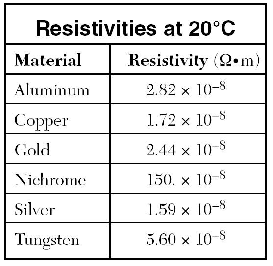
50 ohm coax doesn't have to be made of copper, but copper is a wildly popular choice due to the combination of low resistivity, availability, its relative ease of processing and low cost.
VELOCITY FACTOR
Velocity Factor is a value we use to calculate how much a given conductor will reduce the speed of RF propagation relative to the speed of light if the RF were in free space. Different materials have different velocity factors at different frequencies. For example, a bare copper wire used as a 70cm antenna has a velocity factor of 0.95. If I were making a half wave or quarter wave 70cm antenna, I would determine the length for my desired frequency of 440 MHz and then multiply by 0.95 to get the ideal length for my antenna, adjusted for velocity factor. As you can see, velocity factor is an interesting topic all its own, but does it have anything to do with the 50 ohm question?

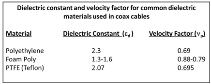
There are many different types of dielectrics with differing permeability. The interesting thing here is that coax is manufactured very intentionally, with great care in the selection of materials, their size and spacing. This all leads us to the answer we are looking for...
CHARACTERISTIC IMPEDANCE
There are two definitions we should be familiar with to help us understand what this is.
- Characteristic Impedance is the input impedance of a transmission line when its length is infinite.
- Characteristic impedance is determined by the geometry and materials of the transmission line and is not dependent on its length.
Let’s say we have a coax transmission line coming out of our amateur radio transceiver. Coax has a center conductor and a shield. There will be a certain amount of current flowing on this transmission line when we use our transceiver. Current will flow in both directions, and it will flow on both the center conductor and the shield.

We could measure the current in amperes. Let’s call this I (I = amps).
We could also measure some voltage between the two conductors. Let’s call this E (E = volts).
There will be a difference of potential between the two conductors all along the transmission line. The physical characteristics of the coax, the spacing, the dielectric material, are engineered such that a given ratio will exist between volts and amps. As one of these values changes, the other must change in ratio.
The ratio is E/I = Zo, where Zo is referred to as the Characteristic Impedance.
If our antenna is a half-wave dipole in free space, then theoretically, it should be free of reactance (also known as a resonant antenna). Notwithstanding the tidiness of OHM'S LAW (R = V/I), note that Zo is not the same thing as a purely resistive load (R = resistance).
REACTANCE
Other factors of impedance come from REACTANCE, the interplay between Inductance (L) and Capacitance (C). In fact, one of the ways we can determine the characteristic impedance of a given coax is to measure its inductance and capacitance per unit of length. The formula is simple: the square root of L divided by C gives us the characteristic impedance in ohms.
DIELECTRICS
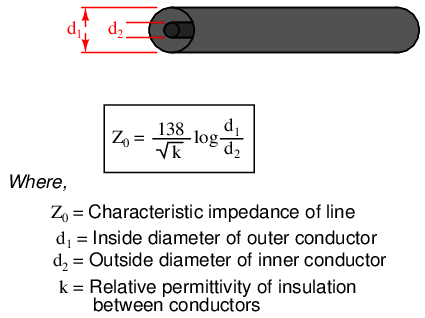
You may be asking, where did that 138 come from in the above formula? Remember the dielectric constant chart we looked at earlier? The formula above expresses the characteristic impedance of a lossless air insulated coax cable.
When coax designers create a recipe for any coax, they have to select a dielectric material which will have a suitable constant as well as velocity factor. They will have to appropriately size the center conductor, dielectric, and shield, and they will have to precisely plan the distance between the conductors in order to achieve the desired ratio for the coax characteristic impedance.
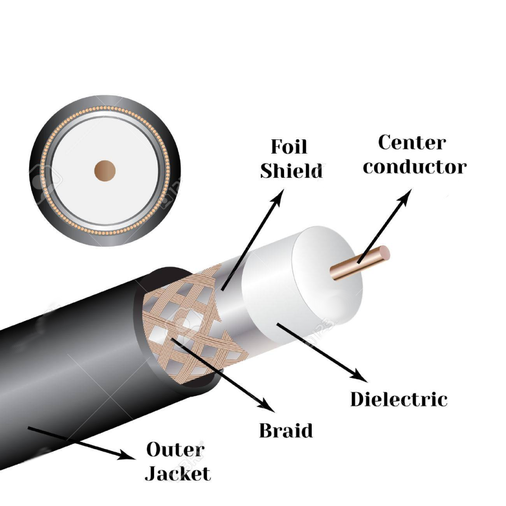
The key takeaway here is that in amateur radio, we have standardized on a characteristic input impedance of 50 ohms. A wide variety of products from many vendors in all parts of the ecosystem adhere to this standard. This fact makes it much easier for us to plan and design well operating systems, where we hope to get as much efficiency as we can with the power that we have. But what happens when something goes wrong?
SWR METERS and IDEAL IMPEDANCE
By using an SWR meter you can measure the voltage standing wave ratio on your transmission line. Remember how we said current would be found on both conductors moving in both directions? What should we expect to happen to voltage measured across these conductors? According to OHM's LAW there is a relationship between these.
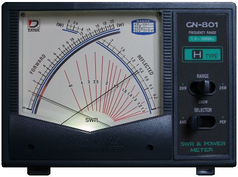
When we look at a VSWR reading we can interpret the result as telling us how close to an ideal impedance we have achieved. This is why, when we have a poor impedance match, we can correct it by using an antenna tuner to add or remove inductance or capacitance. We could also make physical changes to our antenna or other portions of the feed system to affect the real resistance.
FINAL THOUGHTS
A 50 ohm input impedance is a concept. It is a theoretical thing. In practice, we will never have a perfect, ideal system. The fact that all our gear is designed and specified to this characteristic impedance makes it easier for us to get close, or at least as close as we can, to an ideal system.
QUESTION:
How can we maximize power from the transceiver out through the antenna?
ANSWER:
Somehow, match the impedances at the transceiver and the antenna.
That sounds simple enough, but let's dive deeper.
The Maximum Power-Transfer Theorem states that to transfer the maximum amount of power from a source to a load, the load impedance must match the source impedance. But in the case of amateur radio its not quite that simple. We also have to account for the possibility that the feed line between the radio and the antenna has a characteristic impedance, and if it happens to have a length greater than 1/8th of a wavelength of the operating frequency then the feed line itself becomes an important consideration in the overall calculation.
If the impedances aren't matched, maximum power will not be delivered and standing waves will develop along the feed line. Some of that power gets reflected back toward the source. The amount of power lost due to reflection is a function of the reflection coefficient and the standing wave ratio. The greater the impedance mismatch, the larger the losses.
In amateur radio it is often said that an SWR less than 2 is adequate. An SWR of 2 means that reflected power is 10%. Therefore, 90% of the power is reaching the load where it has a chance of being radiated. Add to this the fact that the feed line introduces some loss measured in decibels per foot. So the longer the feed line the greater the loss. There is a two edged sword in all of this. If the source and load are well matched the feed line length will be insignificant. But the worse the match, the source will see a complex impedance that is a function of the feed line length. In short, impedance matching is important.
How can we match Impedance?
Basic electronics theory tells us there are two possible ways to go, but only one of them is helpful for our purposes
- Resistive matching is cheap and frequency insensitive, but dissipates power. That won't help us.
- Reactive matching is power efficient but it is frequency sensitive. This will work, but we have to plan ahead.
To understand this idea of impedance matching a bit better, let's consider a common device - the transformer, and see how it works. A transformer is, in simple terms, an impedance matching device. On one side it has a particular ratio of voltage to current. On the other side it has a different ratio of voltage to current. Remember Ohms Law?
Zsec = the number of turns in the secondary winding
Zpri = the number of turns in the primary winding
Use the formula below to find the sqrt of the Z ratio
Zsec / Zpri = n2
If n = 2, Z ratio = 4; If n = 3, Z ratio = 9; etc
So suppose an antenna with a 450 Ohm impedance is connected on the secondary winding side. Our transceiver with a 50 Ohm impedance is connected on the primary winding side. If Zsec = 9 turns, and Zpri = 3 turns, then the ratio is 3 to 1. The n squared value is 9. The antenna impedance of 450 Ohms, divided by 9, is 50 Ohms, which is what the transceiver wants to see. This transformer looks like it would be an excellent choice to transfer maximum power.
Here are a couple more formulas we should think about. When we build a transformer we are not only affecting resistance. We are changing the relationships of voltage and current as well. We have to plan for this too when we are selecting components to build our transformer, feed line, antenna, etc.
(voltage out) = ((turns ratio) x (voltage in))
(current out) = ((current in) / (turns ratio))


